Simulation Configuration
Configure equipment, fluid properties, and operating parameters for RodSim
The simulation Inputs page has four tabs: Simulation Preferences, Rod Details, Tubing Data, and IPR Data.
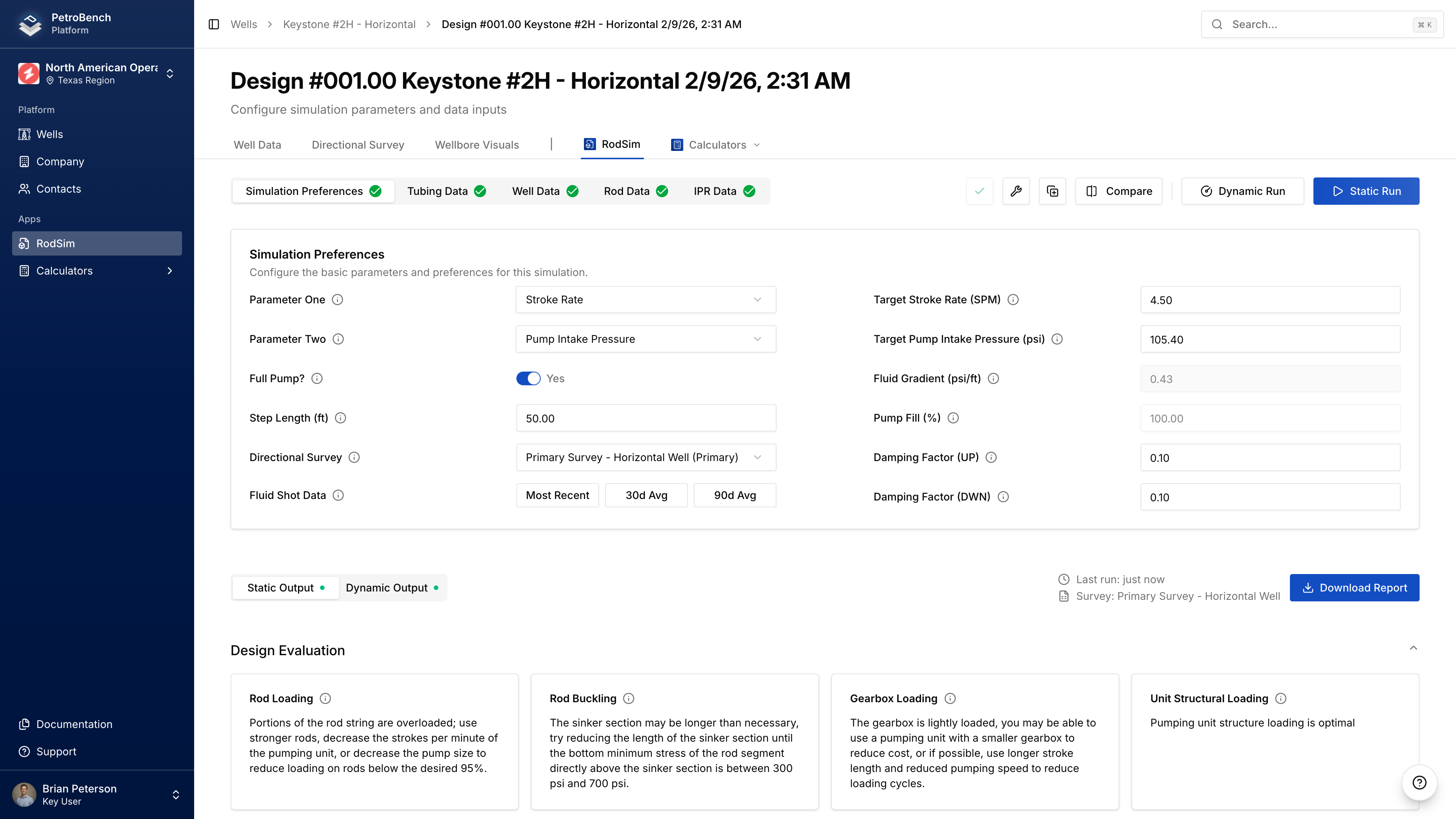
Simulation Preferences
Optimization Parameters
Select what you want to optimize for:
| Parameter | Description |
|---|---|
| Target Production | Desired production rate (BOPD) |
| Target Pumping Speed | Stroke rate (SPM) |
| Target Fluid Level | Producing fluid level depth (ft) |
| Target Pump Intake Pressure | Bottom-hole flowing pressure (PSI) |
Set Parameter One as your primary target and Parameter Two as a secondary constraint.
Click Load from Fluid Shot to populate target fluid level from your well's most recent measurement.
Pumping Unit
- Click Select Pumping Unit
- Filter by manufacturer or search by model number
- Select your unit from the library
If your unit isn't in the library, create a custom unit under Equipment > Pumping Units.
Fluid Properties
| Field | Description |
|---|---|
| Fluid Gradient | PSI per foot (0-0.65) |
| Fluid Above Pump | Distance from pump intake to fluid level (ft) |
Pump Performance
| Field | Description |
|---|---|
| Pump Fill | Percentage of pump barrel filled (0-100%) |
| Pump Condition | Normal, Gas Interference, or Fluid Pound |
| Full Pump Toggle | Forces 100% fill with Gas Interference condition |
Damping & Friction
| Field | Default | Description |
|---|---|---|
| Upstroke Damping | 0.5 | Damping coefficient for upstroke |
| Downstroke Damping | 0.5 | Damping coefficient for downstroke |
| Vertical Friction (Up/Down) | Auto | Rod-tubing friction (lbs) |
Advanced Settings
| Field | Description |
|---|---|
| Use IPR Data | Enable to use well's IPR curve in calculations |
| Step Length | Calculation precision (smaller = more accurate, slower) |
| Directional Survey | Select which survey to use for geometry |
Rod Details
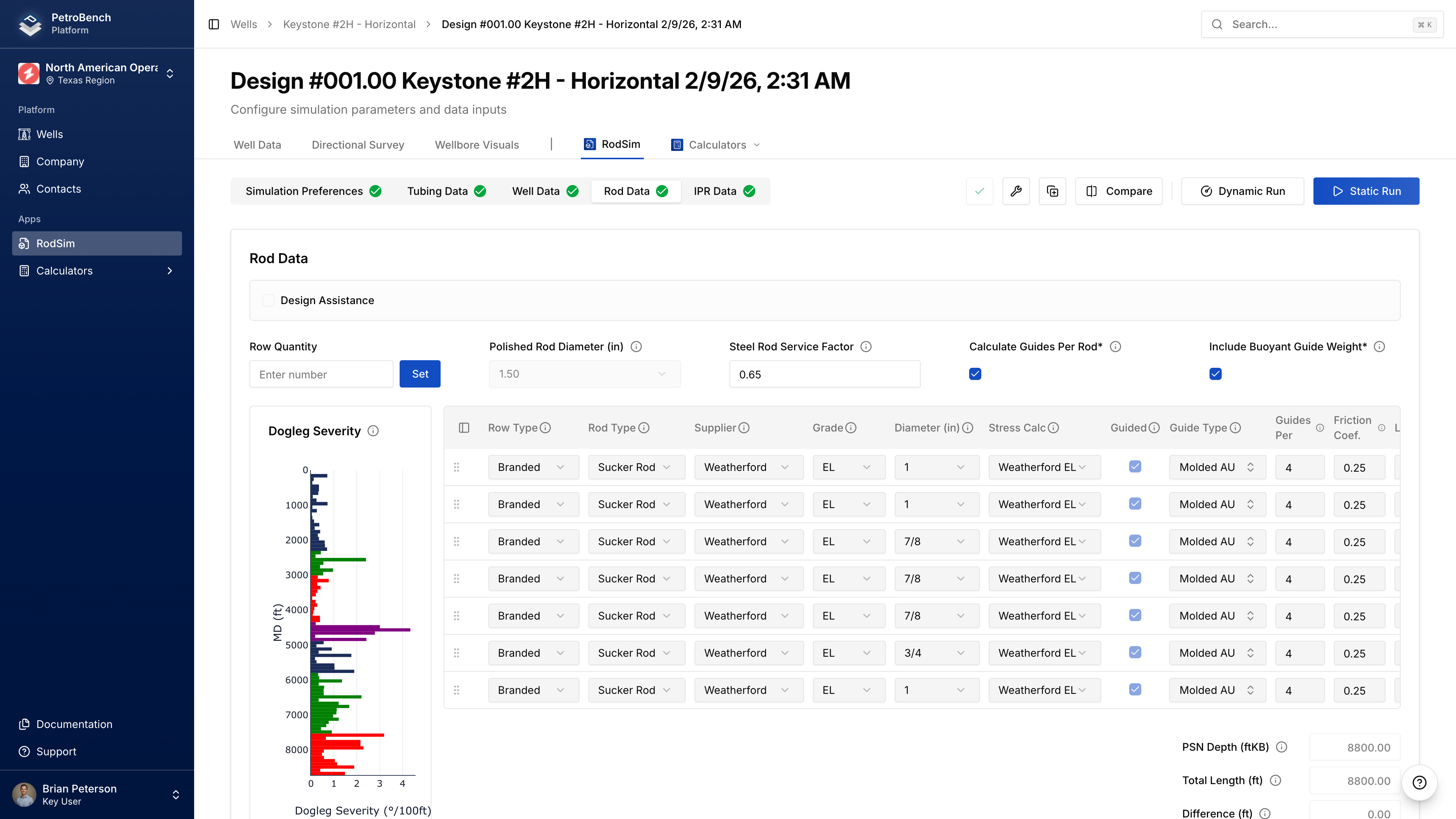
Adding Rod Tapers
Click Add Rod to add a section to your rod string. For each taper:
| Field | Description |
|---|---|
| Rod Type | Sucker Rod, Sinker Bar, or Continuous |
| Manufacturer | Rod manufacturer |
| Grade | Material grade (C, D, K, KD, HS, etc.) |
| Diameter | Nominal size (5/8" to 1-1/8") |
| Length | Length of this section (ft) |
Select Rod Type first - this filters available manufacturers, grades, and diameters.
Rod String Length Validation
Total rod length must be within ±50 feet of PSN depth. If outside this tolerance, you'll get a validation error.
Polished Rod
Select polished rod diameter: 1.00", 1.25", 1.50", 1.75", or 2.00"
Rod Guides
For deviated wells, enable guides on rod sections:
| Field | Description |
|---|---|
| Guided | Enable guides for this taper |
| Guide Type | Molded, snap-on, etc. |
| Guides per Rod | Number per 25 ft rod |
| Friction Coefficient | Guide-tubing friction (default 0.20) |
Custom Rods
If your rod spec isn't in the library:
- Navigate to Equipment > Rods > Custom Rods
- Click Create Custom Rod
- Enter mechanical properties
- Save to organization library
Tubing Data
Pump Setting Depth (PSN)
| Field | Description |
|---|---|
| PSN Depth (MD) | Measured depth to pump (ft) |
| PSN Depth (TVD) | True vertical depth (auto-calculated from survey) |
| PSN Inclination | Wellbore angle at pump (degrees) |
| PSN Dog Leg Severity | Curvature at pump (°/100 ft) |
If you have a directional survey, PSN geometry is calculated automatically.
Tubing Configuration
For each tubing section:
| Field | Description |
|---|---|
| Nominal Size | API size (2-3/8", 2-7/8", 3-1/2", etc.) |
| OD / ID | Outer and inner diameter (inches) |
| Weight | Pounds per foot |
| Grade | Material grade (J-55, N-80, L-80, P-110) |
| Top / Bottom Depth | Measured depths (ft) |
Select nominal size first to filter compatible grades, threads, and weights.
Tubing Anchor
| Field | Description |
|---|---|
| Tubing Anchored | Enable if tubing is anchored |
| Anchor Depth | Depth of anchor (ft MD) |
IPR Data
IPR data improves production predictions by modeling well deliverability.
Reservoir Pressures
| Field | Description |
|---|---|
| Static BHP (SBHP) | Reservoir pressure at mid-perf when shut in (PSI) |
| Bubble Point Pressure | Pressure where gas evolves from solution (PSI) |
| Mid-Perforation Depth | MD to middle of perforated interval (ft) |
Production Test Data
Enter stabilized flow test data:
| Field | Description |
|---|---|
| Test Pressure | Flowing BHP during test (PSI) |
| Test Oil | Oil rate (BOPD) |
| Test Water | Water rate (BWPD) |
| Test Gas | Gas rate (MSCFD) |
Two or more test points at different rates significantly improves IPR curve accuracy.
Deliverability
PetroBench can auto-calculate deliverability parameters from test data, or you can enter them manually:
| Field | Description |
|---|---|
| Deliverability Coefficient (C) | Derived from test data |
| Deliverability Exponent (n) | Typically 0.5-1.0 (0.8 for most oil wells) |
Using IPR in Simulations
- Enter IPR data on this tab
- Go to Simulation Preferences
- Enable Use IPR Data toggle
- Run simulation
Well Data
Additional pump and fluid parameters in the Simulation Preferences section:
Pump Specifications
| Field | Description |
|---|---|
| API Pump Type | Pump designation (RWBC, TRHP, etc.) |
| Pump Diameter | Plunger diameter (inches) |
| Pump Efficiency | Volumetric efficiency (0-100%) |
| Stuffing Box Friction | Friction at wellhead (lbs) |
Fluid Composition
| Field | Description |
|---|---|
| Water Cut | Percentage of water (0-100%) |
| Oil API Gravity | Oil density (API) |
| Water Specific Gravity | Water density relative to fresh water |
| Gas Specific Gravity | Gas density relative to air |
Pressures
| Field | Description |
|---|---|
| Casing Pressure | Annular pressure at surface (PSI) |
| Tubing Pressure | Flowline pressure (PSI, can be negative for vacuum) |
Validation
Before running, PetroBench validates:
- All required fields populated
- Values within valid ranges
- Rod string length within ±50 ft of PSN depth
- Pumping speed below maximum for unit
Missing or invalid fields will show error messages indicating which section needs correction.
Next Steps
- Run the simulation after configuration is complete
- Compare simulations to evaluate design alternatives